Storage Architecture Roundup(Part 2): Type 1 Storage- Scale Up
If you landed on this post, you may want to start with Storage Architecture Roundup (Part 1).
Type 1: Scale Up Storage
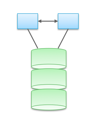
Architecturally, this is the most simple of the three types.
The basic make-up is two controllers in an active/active (both controller serving the same data), active/standby (one controller serving all the data), or active/passive configuration which is sometimes called asymmetric active/active (both controllers serving different subsets of the data).
Client IO Path
The Flow of write IOs through a scale up array goes generally like this:
- Client initiates the IO and transmits it across the network (SAN or IP SAN) to the next hop.
- The IO flows through all the switch hops and lands on the front end port of one of the controllers actively serving IO.
- The controller receives that IO and caches it into memory (generally RAM, sometimes NVRAM, sometimes SSD).
- For data protection purposes, the controller also transmits the IO across an inter-controller link (usually PCIe bus, Infiniband, or other ultra low-latency link) to the other controller which caches the IO into its memory as well, and acknowledges that write back to the first controller.
- Once the controller receives the write acknowledgement from the second controller, it responds back to the client acknowledging the write.
- Depending on the array platform, other things can be done with the write like inline deduplication, compression,etc.
- Some arrays that implement flash-based write caching can stage the writes to flash to clear the RAM for more incoming writes.
- The write is eventually flushed to disk (SSD or Magnetic).
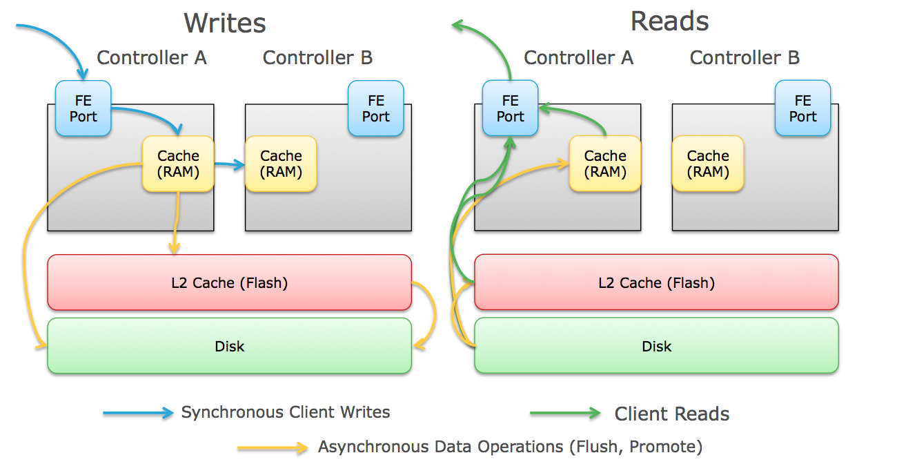
The flow of read IOs is less complicated:
- Client initiates the IO request and transmits it across the network (SAN or IP SAN) to the next hop.
- The request flows through all the switch hops and lands on the front end port of one of the controllers actively serving IO.
- The controller receives the IO request, checks its read cache in RAM for the data and then (depending on the array) checks SSD cache for the data.
- If the data isn't in either location, it's a "read miss" and the data is read directly from the underlying disks (flash or magnetic).
- The controller places a copy of the read in cache (if it was a "read miss") and responds to the client with the requested data.
Characteristics of Scale Up Arrays
Positives
- Inter-controller latency (East/West) is extremely low to the point of being almost negligible. Notice the number/length of blue and green arrows in the diagram above. These are IOs that have to happen while the client is waiting- they are few and relatively short.
- Up to the maximum performance of the controllers, North/South Latency is dependent mainly on the back-end disks.
- Since both N/S and E/W system latency is so low, scale up arrays are great for transactional workloads that max out lower than the system's maximum utilization (<1ms response times possible, read and write)
- The simple architecture and minimal inter-controller communications makes adding advanced data services (compression, deduplication, tiering, etc.) much easier requiring less engineering effort.
- The simple architecture also makes these arrays easy to manage, provision, troubleshoot, and support.
Negatives
- Scale is limited to the horsepower of a single controller or pair of controllers. Most top out at around 1000 drives.
- Availability is provided by controller failover (some systems recommend running controllers at <50% utilization to prevent degradation in performance during failover. Some Architectures that rely on in-controller resources cannot avoid degradation in failover scenarios)
Failure Domains
- For the controllers, the entire controller is generally a failure domain- if something goes wrong (SW, memory board, whatever) it will trigger a failover to the remaining controller.
- Outside of the controllers, the failure domains are more granular- individual disks, downed ports, etc. can generally be overcome without a failover event.
Some Examples
- Active/Standby- Nimble, Pure Storage, Tintri
- Active/Passive- NetApp, EMC VNX*
- Active/Active- HDS HUS, Dell Compellent, EMC VNX*, IBM V7000
*Why is the VNX listed under both? Well newer models can operate A/A on Traditional LUNs (Non-Pool LUNs), but currently Pool LUNs are A/P.
Clustered ONTAP?
I figure I'd address this now. NetApp (both 7-mode and Clustered flavors) is clearly a Type 1 array architecture. The name 'Clustered ONTAP' is actually a very good technical name- It allows for the clustering (or federation) of Multiple NetApp arrays. This technology unlocks some cool features like more seamless inter-array data migrations. That being said, any single NetApp Volume/LUNs is still owned by a single controller as part of a traditional Type 1 active/passive array. Failure domains and performance gates are the same whether your cluster has 1 or 8 NetApp systems as apart of it. This is why you will see NetApp absent in the Type 2a discussion next.